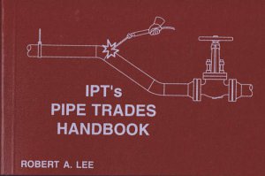
IPTs Pipe Trades Handbook
A105
IPTs Pipe Trades Handbook and Manual – Setting the Standard
Updated in 2006, IPTs Pipe Trades Handbook and Training Manual combine all the essentials of other reference books, plus so much more.
Topics include:
- Pipe and tube data
- Valves, fittings, flanges and gaskets
- Offsets and calculations
- Pipe layout, piping prints, oxy-acetylene set-up, pipe welding, and pipe rigging
- Easy to understand, yet extremely detailed
- Charts written in standard inches and metric
IPT Pipe Trades Handbook for Training or a Job Site Resource
Clear, concise tables and charts and an updated rigging section makes our Pipes Trades Handbook and Training Manual the standard for pipe trades classroom and job site resources. Turn to IPT every time!
-
Shipping info
We ship to most countries of the world with the exclusion of Portugal, Niger, and Nigeria.
-
Payment methods

-
Return Policy
Take a look at our return policy for full details.
IPTs Pipe Trades Handbook and Manual – Setting the Standard
Updated in 2006, IPTs Pipe Trades Handbook and Training Manual combine all the essentials of other reference books, plus so much more.
Topics include:
- Pipe and tube data
- Valves, fittings, flanges and gaskets
- Offsets and calculations
- Pipe layout, piping prints, oxy-acetylene set-up, pipe welding, and pipe rigging
- Easy to understand, yet extremely detailed
- Charts written in standard inches and metric
IPT Pipe Trades Handbook for Training or a Job Site Resource
Clear, concise tables and charts and an updated rigging section makes our Pipes Trades Handbook and Training Manual the standard for pipe trades classroom and job site resources. Turn to IPT every time!
-
ManufacturerIPT Publishing & Training LTD.
-
Publication Date1991
-
Book Size3.88 x 5.88 x 1
-
Pages534
-
Edition11th Edition (2008)
-
CoverSoft, Perfect Bound
-
AuthorRobert A Lee
-
ISBN 100920855180
-
ISBN 139780920855188
Shipping Methods
Most of our orders are shipped in the way that is most time efficient and cost effective. In example, if you have a small order that is going to California it will be shipped by USPS Priority, as it is the most time efficient and cost effective. However, since we are in North Carolina, a small order may be sent by UPS Ground to some parts of Virginia, North Carolina, and South Carolina since it will arrive next day. If you are needing a package shipped by a specific carrier please let us know in the "Customer Notes" during the Checkout process. We are not held responsible for packages that are not delivered to you for lack of information. All international packages will be shipped by USPS Priority Express International unless otherwise chosen during the Checkout process.
Our shipping hours are from 9:00 a.m. to 2:30 p.m. Eastern Standard Time. All USPS Priority orders need to be in before 12 p.m. EST to guarantee same day shipping. Any orders placed after 2:30 p.m. EST will be processed and shipped on the next business day. In example, orders that are placed Wednesday evening with UPS 2nd Day Shipping will be shipped out Thursday afternoon and will arrive the following Monday.
Although we will be offering UPS Next Day or UPS 2nd Day, if your package does not get there on time, you will not be refunded for the shipping costs. We cannot control how UPS or USPS operates.
Also, we are limiting our international shipping to countries that have opened their borders to trade with the US. If you do not see your country listed during Checkout, please email us. After placing your order, you will receive an email confirming you understand that there will be delays with shipping out of the US. If you do not respond after a second email notification, your order will be cancelled.
International orders will be shipped once we have verified that we have all items ordered in stock. If an item is on backorder from the manufacturer we will notify you immediately. We will not do partial shipments to anywhere outside of the US. Customs Fees and Import Taxes are not part of Shipping Costs. These duties/fees are the buyer's responsibility. We will email you immediately upon receipt of an international order to confirm your understanding of this. If a package is refused due to Customs Fees or Import Taxes and returned to us, you will be refunded for the price of the products only. We request that you contact your local custom's office to find out more information about these fees and taxes before ordering from us.
Due to the nature of some of our items (i.e. size vs weight ratio) there will be added freight to certain items. Please look over your items carefully and if you have any questions contact us.
We accept the following payment methods:

If you are a business that is already established with us for Net 30 Terms, then you are more than welcome to place an order by Purchase Order and we will be glad to fulfill it for you.
Our Return Policy
If you need to return an item, e-mail us at info@pipefitter.com or call us at 910-592-1310 within 30 days of receipt for instructions. You will receive further instructions with a Return Authorization number. The Return Authorization number MUST be on the package. Any returns requested after 30 Days will be issued a 20% Restocking Fee.
Freight charges for returns/exchanges will be the responsibility of the customer. Pipefitter.com claims no responsibility for missing shipments.
All returns must be in resalable condition, and containing all the original contents.
Merchandise that has been used or show any signs of abuse cannot be returned for refund or exchange. You may be under warranty and must work with the manufacturer to resolve the issue. We will pay freight charges for the return of defective items or if we made a mistake on your original order. Any packages that are returned to us for "Incomplete Address", "Insufficient Address", or "Address - Not Known", will be held at our facility. The customer will be responsible for the second Shipping Cost to the full amount or if requested refunded for the products only.
Returned Merchandise Credits
Credit will be evaluated for each returned item individually. We will refund item costs only. Once an item is received you will be contacted so that we may process your return.
Reasons for Return
Exchange or Credit
All returns will be inspected upon receipt. Upon approval of receipt you will either be credited the monetary value or the monetary value will be put towards an exchange. You will either be credited or charged the remainder of the new order.
If you received your item as a gift, you will need to provide your own form of payment if necessary.
Functional or Visual Defects
We inspect all merchandise before we ship it. In the event that your merchandise is defective, it can be handled in one of the following ways:
“Out of the box” visual defects must be reported within 30 days of receipt.
Functional defects must be reported to the manufacturer. Here’s a list of the manufacturer’s information.
Refunds
Upon an approved receipt you will be contacted for the original payment method of your order. Eligible refunds will be credited to that method of payment. If that payment method declines you will be notified of the situation and another payment method will need to be provided.


